
 English
 中文简体
中文简体 русский

 Read More

Product Category
NEW Category
Contact us
Contact Us
We specialise in the research, development and manufacture of electrical wires and cables.
 +86-15021943462
Difference Between Induction and Synchronous Motor: Principles and Torque Guide
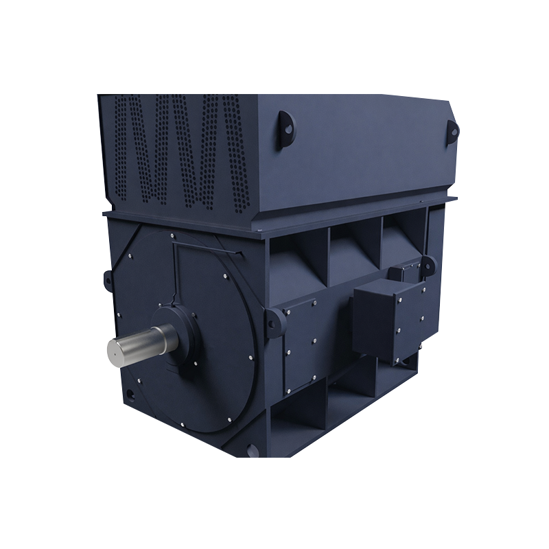
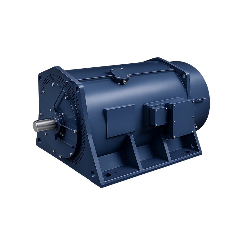
Electric motors convert electrical energy into mechanical rotation, and the specific way they accomplish this defines their operating characteristics, efficiency, and suitability for different applications. The two fundamental AC motor types—induction and synchronous—account for the vast majority of industrial and commercial motor installations. Understanding the difference between induction motor and synchronous motor is essential for selecting the right machine for a given load, as their speed behavior, starting methods, and efficiency profiles differ markedly. Beyond motor type, practical motor integration requires knowledge of torque production, efficiency calculations, speed control, gear reduction, and the ability to diagnose common failures. This comprehensive guide brings together the working principles, key equations, and real-world problem-solving strategies that engineers and technicians need to optimize electric motor systems, whether working with a large industrial drive or a single phase asynchronous motor in a domestic appliance.
Content
- 1 The Fundamental Difference Between Induction Motor and Synchronous Motor
- 2 Synchronous Motor Working Principle and Starting Methods
- 3 Single Phase Asynchronous Motor: Design and Domestic Applications
- 4 Parallel Shaft Motors and Drives: Gear Reduction Integration
- 5 Motor Torque Equation and Efficiency Formula
- 6 Motor Rotates in Which Direction: Determining and Changing Rotation
- 7 Speed Controller for Electric Motor: VFDs and DC Drives
- 8 Common Electric Motor Problems and Solutions
The Fundamental Difference Between Induction Motor and Synchronous Motor
The primary difference between induction motor and synchronous motor lies in the relationship between rotor speed and the rotating magnetic field produced by the stator. In a synchronous motor, the rotor rotates at exactly the same speed as the stator's magnetic field—the synchronous speed, given by Ns = 120f / P, where f is the supply frequency and P is the number of poles. The rotor is magnetized either by permanent magnets or by a DC field current fed through slip rings, locking it into step with the rotating field. An induction motor, by contrast, operates with a small difference in speed called slip, typically 2–5% at full load. The rotor consists of short-circuited bars (a squirrel cage) that develop current and a magnetic field only when the rotor speed is less than synchronous speed, inducing a voltage in the rotor conductors. This slip is what generates torque; without it, no rotor current flows and no torque is produced.
This speed difference dictates their application strengths. Synchronous motors maintain constant speed regardless of load variation, making them ideal for precision drives such as compressors, large pumps, and generators. They can also be designed to operate at a leading power factor, compensating for lagging reactive power in a plant. Induction motors, particularly the rugged squirrel-cage type, dominate general industrial applications due to their simple construction, low cost, and ability to start directly on-line. However, their speed drops slightly with increasing load, and they always draw lagging reactive power from the supply. A practical example: a 4-pole synchronous motor on a 60 Hz supply runs at exactly 1,800 RPM, while an equivalent 4-pole induction motor might run at 1,750 RPM at full load, with the 50 RPM slip enabling torque production.
Synchronous Motor Working Principle and Starting Methods
The synchronous motor working principle relies on magnetic locking between the stator's rotating field and the rotor's constant magnetic field. When three-phase AC is applied to the stator, it produces a rotating magnetic field. The rotor, already excited with DC, acts as a permanent magnet. Opposite poles attract, and the rotor is pulled along at synchronous speed. However, a significant challenge is starting: at standstill, the rotating field moves too quickly for the rotor to lock in from rest. Most synchronous motors therefore incorporate a squirrel-cage damper winding in the rotor face, allowing the motor to start as an induction motor. Once the rotor reaches approximately 95% of synchronous speed, the DC field is energized, and the rotor pulls into synchronism. Modern permanent magnet synchronous motors (PMSMs), increasingly used in servo drives and electric vehicles, avoid the excitation slip rings and achieve high efficiency and power density, but they require a variable frequency drive (VFD) to start and control speed smoothly.
Single Phase Asynchronous Motor: Design and Domestic Applications
A single phase asynchronous motor is an induction motor designed to operate on a single-phase AC supply, typically found in household appliances, fans, and small pumps. The fundamental challenge is that a single-phase stator winding produces a pulsating magnetic field, not a rotating one, and therefore cannot generate starting torque by itself. To create the necessary rotating field, various starting methods are employed. The most common is the capacitor-start motor, which uses an auxiliary winding physically displaced from the main winding and connected in series with a capacitor to create a phase-shifted current. This produces a two-phase field that starts the rotor; a centrifugal switch then disconnects the auxiliary circuit at about 70–80% of full speed. Other designs include the split-phase (resistance-start) motor and the permanently split capacitor (PSC) motor, which keeps the capacitor in circuit for improved running performance. These motors are inherently less efficient than their three-phase counterparts for a given power rating—typical efficiencies range from 50% for fractional horsepower units to 75% for larger models—but their compatibility with standard single-phase outlets makes them irreplaceable in domestic and light commercial settings.
Parallel Shaft Motors and Drives: Gear Reduction Integration
Parallel shaft motors and drives refer to motor-gearbox combinations where the output shaft is parallel to the motor shaft, with torque transmitted through helical or spur gears. This configuration is a subset of gear reducer for electric motor systems and is widely used in conveyors, material handling, and packaging machinery. The gear reducer serves two critical functions: it reduces the high rotational speed of the motor to a usable low speed, and it multiplies the torque. For a given gear ratio i, the output speed Nout = Nmotor / i, and the output torque Tout = Tmotor × i × ηgear, where ηgear is the gearbox efficiency (typically 94–98% per stage for helical gears). A parallel shaft arrangement is compact and efficient, often allowing the motor to be mounted directly onto the driven machine. When selecting a parallel shaft gearmotor, the service factor—the ratio of the gearbox's rated capacity to the actual load—must be considered. For uniform loads, a service factor of 1.0–1.25 is acceptable, while for shock loads or frequent starts, a factor of 1.5–2.0 or higher is recommended to prevent premature gear wear.
Motor Torque Equation and Efficiency Formula
The mechanical output power of a motor is related to torque and speed. The fundamental equation for torque of a motor in terms of power and rotational speed is:
T = (60 × Pout) / (2π × N) (torque in Nm, power in W, N in RPM)
For a DC motor, the electromagnetic torque is also proportional to the armature current and magnetic flux: T = kt × φ × Ia. The torque constant kt depends on motor construction. In AC induction motors, the torque developed is proportional to the square of the applied voltage and varies with slip.
The formula of efficiency of motor relates electrical input to mechanical output:
η = (Pout / Pin) × 100%
For a three-phase AC motor, Pin = √3 × VL × IL × cosφ, where cosφ is the power factor. Losses include stator copper losses (I²R), rotor copper losses, iron losses (hysteresis and eddy currents), mechanical friction and windage losses. For example, a 15 kW, 4-pole IE3 induction motor might achieve 91.5% efficiency at full load, dropping to 88% at 50% load. Minimizing these losses through high-grade electrical steel, optimized slot design, and improved cooling is the focus of premium efficiency motor standards like IE4 and IE5.
Motor Rotates in Which Direction: Determining and Changing Rotation
The direction in which a motor rotates is determined by the interaction of the magnetic fields. For a three-phase induction motor, the phase sequence of the supply determines the direction of the rotating stator field. By convention, if the motor is connected so that the phase sequence is L1, L2, L3 at terminals U, V, W, the shaft rotates clockwise when viewed from the drive end. Reversing any two supply leads reverses the phase sequence and thus reverses the motor's rotation direction. This is standard practice when commissioning a motor-driven pump or conveyor. For a DC motor, the direction of rotation follows Fleming's left-hand rule: reversing either the armature current or the field current reverses rotation, but reversing both leaves rotation unchanged. A permanent magnet DC motor reverses with the polarity of the applied voltage. When operating a motor, the designated direction of rotation is often indicated by an arrow on the housing; running a motor in reverse of its intended direction can damage certain loads, such as screw pumps or fans with directional impellers.
Speed Controller for Electric Motor: VFDs and DC Drives
A speed controller for electric motor varies the motor's rotational speed by adjusting the electrical input parameters. For three-phase induction motors, the standard device is the Variable Frequency Drive (VFD), which rectifies incoming AC to DC and then inverts it to a variable-frequency, variable-voltage AC output. By maintaining a constant V/f ratio, the motor's torque capability is preserved across a wide speed range—typically from 10% to 150% of base speed. For a DC motor, a thyristor or PWM-based DC drive varies the average armature voltage, directly controlling speed. Modern sensorless vector control algorithms allow VFDs to control induction motor speed and torque with an accuracy of ±0.5% of rated speed without a feedback encoder, making them suitable for demanding applications such as crane hoists, extruders, and textile winding machines. For small single-phase motors, simpler triac-based voltage controllers or electronic soft starters are common.
Common Electric Motor Problems and Solutions
Diagnosing electric motor problems and solutions systematically extends motor life and prevents unplanned downtime. The most common issues, their probable causes, and appropriate corrective actions are summarized below.
| Problem | Possible Causes | Solution |
|---|---|---|
| Motor overheating | Overload, poor ventilation, bearing failure, high ambient temperature | Reduce load, clean fan cover, replace bearings, verify duty cycle |
| Excessive vibration | Misalignment, imbalanced rotor, loose foundation bolts, worn bearings | Realign shafts, dynamic balance rotor, tighten mounting, replace bearings |
| Motor fails to start | Blown fuse, tripped overload, open winding, single-phasing (3-phase) | Check supply fuses and relays, test winding resistance, verify all phases present |
| Bearing noise / failure | Insufficient lubrication, contamination, excessive belt tension, shaft currents | Relubricate or replace bearings, install shaft grounding ring, align belt drive |
Regular preventive maintenance—insulation resistance testing with a megohmmeter, thermographic inspection of connections, and bearing vibration trending—can detect these issues before failure occurs. For electric motor problems and solutions, keeping a log of operating hours and load profiles helps determine when to replace bearings (typically every 20,000–40,000 operating hours) or regrease. When a motor fails, a root cause analysis is essential: simply replacing the motor without identifying why it failed—be it moisture ingress, voltage imbalance, or a jammed gear reducer—will lead to a repeat failure.
PREV:GOST vs IEC Standard Motors: Key Design, Testing, and Certification Differences
NEXT: Working Principle of DC Motor: Components, Efficiency and Speed Guide
NEXT: Working Principle of DC Motor: Components, Efficiency and Speed Guide
Interested in cooperation or have questions?
Let'S Work Together Welcome Aboard!
-

-
 +86-15021943462
 -
 Room 2326, 23rd Floor 2000 Zhongshan North Road Putuo District Shanghai, China
Join Our Mailing List
Product Categories
Quick Links
Quick Links
