
 English
 中文简体
 русский


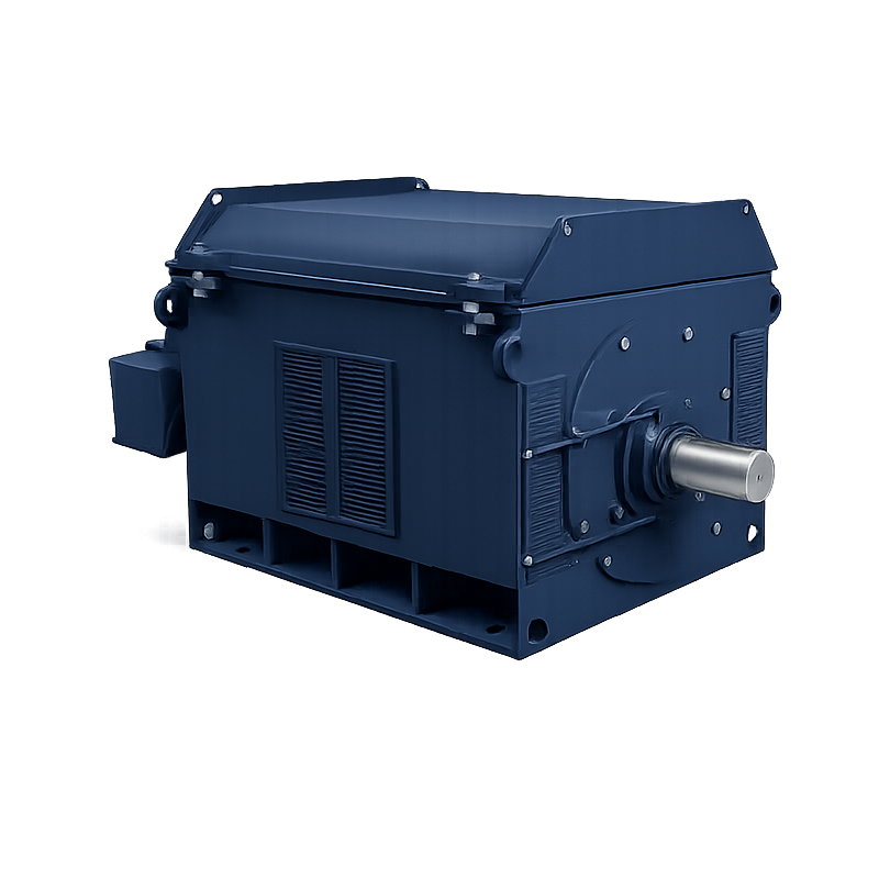
 Read More

Product Category
NEW Category
Contact us
Contact Us
We specialise in the research, development and manufacture of electrical wires and cables.
 +86-15021943462
Related News
- Why General Purpose Synchronous Motors Are Essential for Continuous Industrial Operations?
- New High-Efficiency Energy-Saving Motor Debuts, Boosting Industrial Energy Efficiency
- DC Motors Explained: Working Principle, Types & Brushed vs Brushless
- Metallurgical Motor Specifications: What Matters Most in Mill Duty Selection
Most Common Motor Failures in Continuous Industrial Operations Explained
A 1,250 kW ball mill drive in a continuous concentrator does not stop gradually. It stops the moment a bearing seizes, a winding fails, or a protection relay trips on a 130 degrees Celsius winding alarm.
The most common motor failures in continuous industrial operations follow a short, repeatable list rather than random bad luck. Reliability data compiled in IEEE 493, widely known as the Gold Book, attributes roughly 41 percent of induction motor failures to bearings, 37 percent to stator winding insulation, 10 percent to rotor faults, and the remaining 12 percent to shaft, frame and external causes.
Two components, bearings and stator windings, therefore account for close to four out of five unplanned motor stops. Inspection intervals, spare motor inventory and selection criteria should be built around that ratio. When a drive is replaced, the strongest specification document is the failure history of the machine it supersedes, and the same logic drives severe-duty motor selection in mining, metallurgy and cement plants.
10 C Sustained temperature rise above the insulation class limit that halves the remaining life of a stator winding.
1 to 6 One percent of line voltage unbalance can push current unbalance to roughly six percent, and the hottest phase carries the extra heat.
Content
- 1 The Four Failure Modes That Dominate Continuous Industrial Operations
- 2 Why Bearings Fail First in Continuous Duty
- 3 Stator Winding Insulation Failures Run on a Thermal Clock
- 4 Rotor Failures Cluster in High-Torque and High-Inertia Drives
- 5 Environmental Failure Drivers: Dust, Humidity and Hazardous Areas
- 6 A Five-Step Inspection Routine That Catches Motor Failures Early
- 7 Frequently Asked Questions About Motor Failures
The Four Failure Modes That Dominate Continuous Industrial Operations
Bearings, stator winding insulation, rotor cages, and shaft or frame faults explain almost every unplanned motor failure in continuous duty, and the first two alone are responsible for about 78 percent of breakdowns.
Failure mode: the specific physical process, thermal, electrical, mechanical or environmental, that degrades a motor component until the machine can no longer deliver rated torque at its rated duty. Naming the mode is what separates a repair from a fix.
Share of induction motor failures by component, IEEE 493 reliability data, scale 0 to 50 percent
Bearings
41%
Stator windings
37%
Shaft and frame
12%
Rotor
10%
Figures are the widely cited distribution for induction machines operating in continuous industrial service.
- Bearings: mechanical fatigue, lubrication breakdown, contamination and electrical erosion of the raceway.
- Stator insulation: thermal aging, partial discharge above 6 kV, moisture and conductive dust bridging the winding.
- Rotor: broken bars and cracked end rings caused by repeated thermal cycling during heavy starts.
- Shaft and frame: misalignment, foundation movement, cooling failure and mechanical damage from the driven equipment.
Why Bearings Fail First in Continuous Duty
Bearings lead every failure ranking because they are the only motor component exposed to mechanical load, electrical current and lubricant chemistry at the same time, and continuous operation removes the idle periods that let them recover.
Lubrication starvation and grease degradation
Grease is a consumable with a shelf life measured in running hours, not calendar years. A practical rule used by maintenance teams is that grease service life halves for roughly every 15 degrees Celsius above 70 degrees Celsius measured at the bearing housing. Over-greasing is just as damaging as under-greasing, because excess grease churns, raises internal friction and pushes the operating temperature higher. Mixing two incompatible thickener bases produces the same result as running dry.
Electrical erosion from shaft currents
Variable frequency drives create common-mode voltage that finds a path through the shaft, the bearing and the frame. Once shaft voltage exceeds the dielectric strength of the oil film, micro-discharges pit the raceway and produce the fluted, washboard pattern that signals electrical erosion rather than mechanical fatigue. Insulated bearings on the non-drive end and a shaft grounding ring on the drive end are standard countermeasures on motors above roughly 90 kW.
Misalignment, overhung load and thermal growth
A parallel offset of 0.05 mm at the coupling hub is already outside typical alignment tolerances for high-speed drives, yet it is invisible to the eye and audible only as a slight rise in vibration. Belt-driven and overhung loads multiply radial force on the front bearing, while thermal growth during a four-hour startup shifts alignment after the machine is already running.
41% Share of motor failures attributed to bearings
0.05 mm Coupling offset that already exceeds typical alignment tolerance
70 C Bearing housing temperature above which grease life falls quickly
Stator Winding Insulation Failures Run on a Thermal Clock
Stator insulation fails on a thermal clock: every 10 degrees Celsius of sustained temperature rise above the insulation class limit halves the remaining life of the winding, which is why overload alone rarely destroys a motor and a blocked cooling duct always does.
| Insulation class | Maximum winding temperature | Typical continuous-duty application |
| Class B | 130 C | Legacy machines and light process duty |
| Class F | 155 C | Modern high-voltage induction motors |
| Class H | 180 C | Mill, crusher and metallurgical duty |
A motor running 20 degrees Celsius cooler than its class limit can outlast the same machine running at the limit by a factor of four.
Failure consequence of the 10-degree rule applied to winding insulation life
Above 6 kV, partial discharge becomes the second mechanism. Contaminated windings, humidity and voids inside the insulation system allow small discharges that slowly erode the dielectric until a flashover occurs during a normal start. Long cable runs between the drive and the motor make it worse by roughly doubling the reflected wave voltage at the terminals.
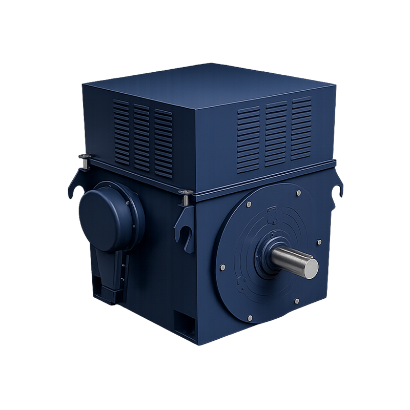
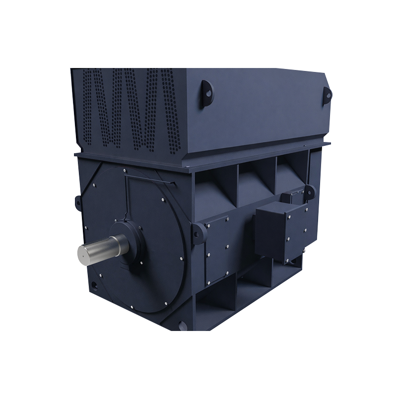
For dust-heavy continuous duty, high-voltage squirrel cage AC motors are commonly supplied with IP54 enclosures and closed-circuit cooling, which keeps conductive dust out of the winding and holds the temperature rise inside the class limit under steady load.
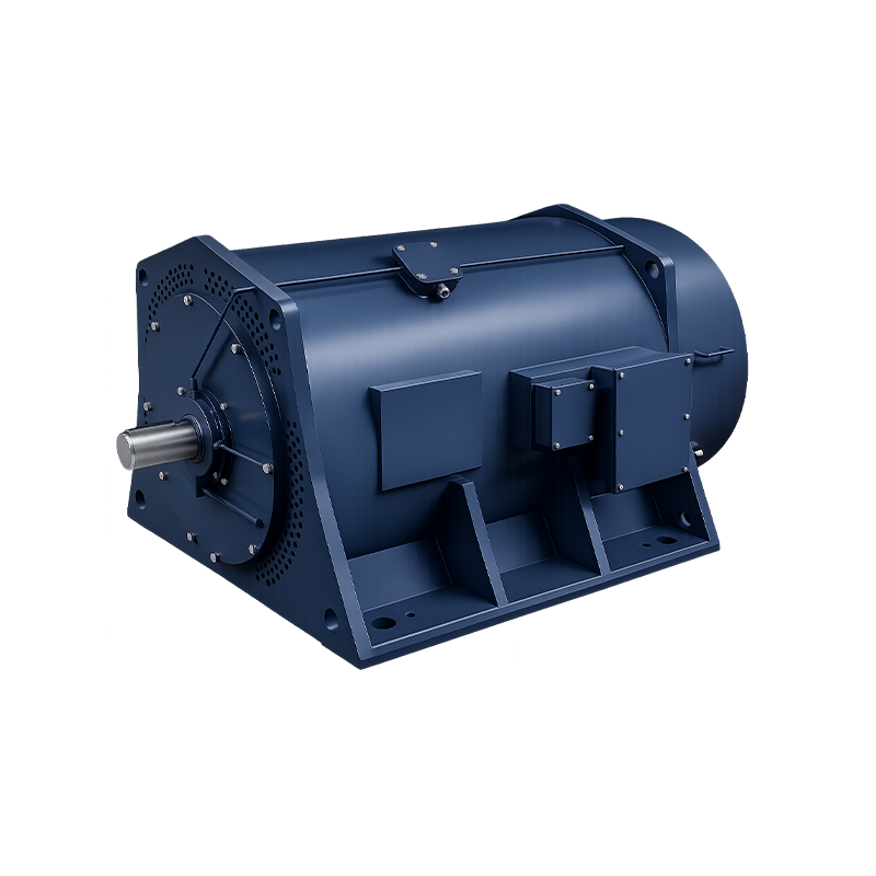 GOST Standard IP54 IC511 High Voltage Squirrel Cage Electric MotorQ: Do you provide motor selection and technical consulting services? We provide professional motor selection and technical consulting based on operating conditions, ap...View Product →
Rotor Failures Cluster in High-Torque and High-Inertia Drives
Rotor faults are the third-largest failure category, and they concentrate almost entirely in drives that start frequently, start under load, or reverse direction.
During a direct-on-line start, the rotor carries five to seven times full load current until it accelerates. Each start heats the bars and the end ring joints at different rates, and after a few thousand cycles the mechanical stress cracks the joint. Current signature analysis detects the resulting sidebands around the supply frequency long before a bar lifts out of the slot and damages the stator.
- Grinding and crushing circuits with high inertia and three to five starts per hour
- Crane and metallurgical drives with reversing duty and frequent plugging
- Excavator and heavy mining equipment exposed to shock loading and dust
Where starting torque and current control matter more than simplicity, wound rotor machines with slip ring starting or heavy-duty synchronous motors designed for ball mills and crushers handle the same load profile with far less rotor stress.
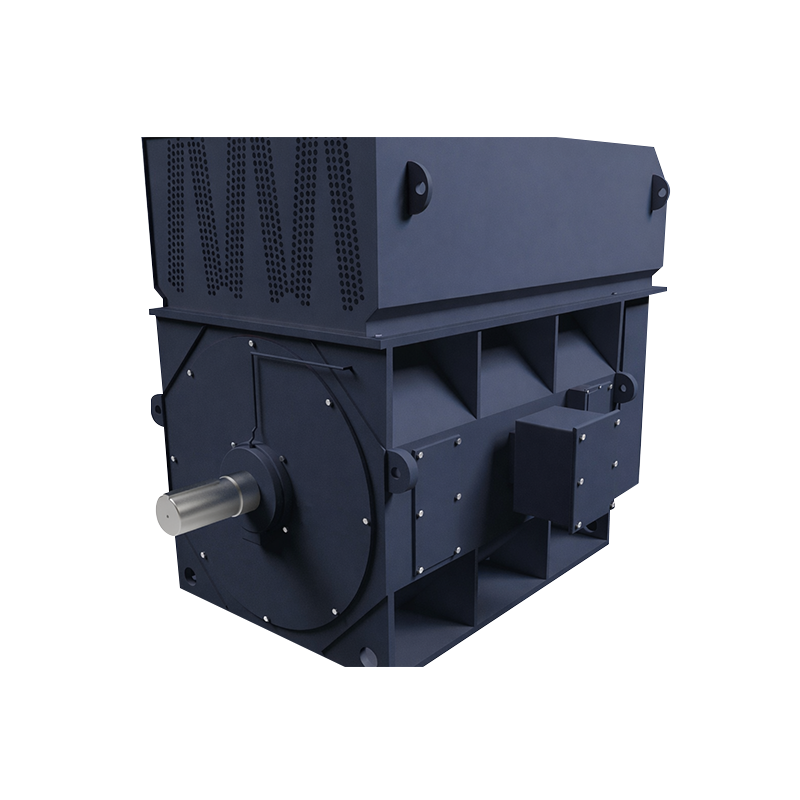
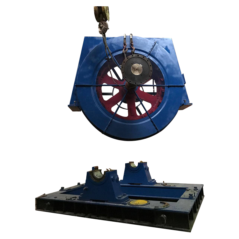 SDM/SDMZ Series Heavy-duty High-Voltage Synchronous Motors for Ball MillsThe SDM and SDMZ series high-voltage synchronous motors are purpose-engineered for ball mill applications in mining, cement, and heavy industrial sectors. Designed to ...View Product →
Environmental Failure Drivers: Dust, Humidity and Hazardous Areas
In dusty, humid or explosive atmospheres, contamination overtakes overload as the leading cause of winding failure, and the enclosure selection made at purchase determines how soon that happens.
Open cooling: IP23 with IC01
- Air is drawn directly across the winding and expelled
- Highest cooling efficiency and lowest cost per kilowatt
- Requires clean, dry, non-hazardous plant air
- Conductive dust and moisture reach the insulation directly
Closed cooling: IP54 with IC511 or IC516
- Air circulates inside a sealed frame through a heat exchanger
- Dust, humidity and corrosive gas stay outside the winding
- Slightly lower efficiency and higher initial cost
- Preferred for cement, mining, chemical and outdoor installations
In explosive atmospheres the requirement is stricter still: the enclosure must contain an internal ignition without transmitting it to the surrounding gas or dust, and the motor must be certified for the specific zone and temperature class. Export suppliers such as ICEM Electric (Shanghai Menti Electromechanical Trading Co., Ltd.) therefore carry both GOST and IEC versions of the same frame, since Russian and Central Asian projects specify GOST while European projects specify IEC.
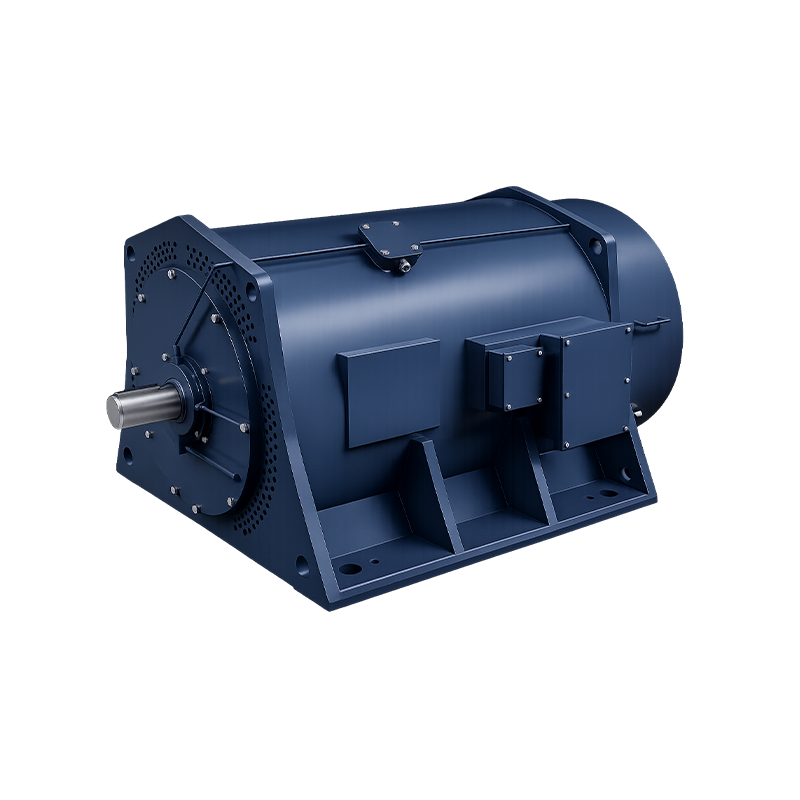
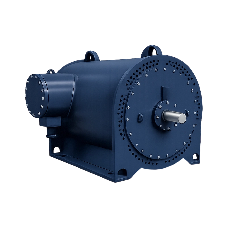 GOST Standard IP54 IC511/IC516 Squirrel-Cage High-Voltage Explosion-Proof Asynchronous MotThe GOST standard IP54 IC511/IC516 squirrel-cage high-voltage explosion-proof asynchronous motor is designed for safe and reliable operation in hazardous environments ...View Product →
A Five-Step Inspection Routine That Catches Motor Failures Early
A five-step routine built around vibration, temperature, insulation and current detects the four dominant failure modes weeks before they trip a drive, and it costs far less than a single unscheduled production stop.
Record a baseline at commissioning
Log vibration velocity in millimeters per second, bearing temperature, winding resistance and insulation resistance while the machine is known to be healthy. Every later judgement is a comparison against this record.
Trend vibration and temperature monthly
Investigate any rise of 2 mm/s in vibration velocity or 10 degrees Celsius in bearing temperature above baseline. A steady trend matters more than a single high reading.
Check insulation quarterly
Measure insulation resistance and the polarization index. A polarization index below 2.0 points to moisture or contamination inside the winding, both of which precede a flashover.
Audit lubrication by running hours
Re-grease at the interval stated for the actual speed, frame size and bearing temperature, never by habit. Record every application so the next technician knows what went in and when.
Review current balance and thermal images
Phase current unbalance above 5 percent or a hot connection on the terminal box indicates a developing problem in the supply, the rotor or the winding itself.
Applied consistently, the routine converts most motor failures from emergencies into planned interventions, and it produces the evidence needed when a replacement machine has to be specified for the same duty.
Frequently Asked Questions About Motor Failures
What is the most common cause of motor failure in continuous operation?
Bearings, at roughly 41 percent of failures according to IEEE 493 reliability data. Lubrication breakdown, contamination and shaft current erosion account for most of those bearing failures, and stator winding insulation follows at about 37 percent.
How often should continuous-duty motor bearings be greased?
Follow the manufacturer interval expressed in running hours, which typically falls between 2,000 and 4,000 hours for medium and large machines. Shorten the interval when bearing temperature runs above 70 degrees Celsius, and never mix incompatible grease types in the same housing.
Can a failed motor be repaired, or should it be replaced?
Rewinding is usually economical when the damage is limited to one phase and the core is undamaged. Replace the machine instead when the rotor is scored, the frame is distorted, or the rewind would drop efficiency by more than two percentage points on a motor that runs continuously.
Which motor type copes best with frequent starts and high inertia?
Heavy-duty synchronous motors are preferred for ball mills and crushers because they tolerate high inertia and provide power factor correction. Wound rotor slip ring machines control starting current where torque demand is the limiting factor, while standard squirrel cage motors rely on soft starters to limit thermal cycling.
PREV:Metallurgical Motor Specifications: What Matters Most in Mill Duty Selection
NEXT:Why Choosing the Right Motor Supplier Reduces Project Downtime on Heavy Lines
NEXT:Why Choosing the Right Motor Supplier Reduces Project Downtime on Heavy Lines
Interested in cooperation or have questions?
Let'S Work Together Welcome Aboard!
-

-
 +86-15021943462
-
 Room 2326, 23rd Floor 2000 Zhongshan North Road Putuo District Shanghai, China
Join Our Mailing List
Product Categories
Quick Links
Quick Links
